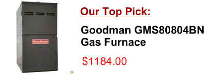
[post_title]
Description:
Warm Air Gas Furnace The A95UH/A93UH/95G1UH & 92G1UH Category IV gas furnace is shipped ready for installation in the upflow or If necessary, run the condensate line into a condensate pump to meet drain line slope requirements.
Product Description of [post_title] below:
Domestic Shipping: This item is also available for shipping to select countries outside the U.S.
International Shipping: This item is not eligible for international shipping.
Average Customer Review: 9/10
COLLECTION GAS FURNACE UPFLOW / HORIZONTAL AIR DISCHARGE 506610−01 05/2011 Supersedes 12/2010 multiple furnace installation may use a group of up to densate trap, condensate pump must be used. Con-
Of your outdoor heat pump unit. NOTE: 6 32-5064-WEB01 Safety Section – Gas Furnaces BURN HAZARD with your furnace, condensate drains should be checked and cleaned periodically to assure that condensate can drain freely from coil to drain.
The ML193DF Category IV gas furnace is shipped ready for installation in the downflow position. condensate pump must be used. Condensate drain Refer to figure 51 for field wiring and figure 52 for schematic
CONDENSATE TRAPS Condensate drain pan H/2 minimum Fan inlet pressure (negative) H = Fan inlet pressure (in. W.C.) + 1 in. Initial sea levels when fan starts H FIGURE 2. condensate traps, ho wever, a couple of simple, standard drawings in a designer’s
Heat Pump Wiring Diagrams 38AYC, 38BYC, 38BYG, 38YCC, 38YCG, 38YCS, 38YCW, 38YKC unit operates with a suction gas superheat at the compressor inlet CONNECTION DIAGRAM SCHEMATIC DIAGRAM (LADDER FORM) 1. Compressor damage may occur if system is over
Gas Furnace. 681292-UIM-A-0211 Johnson Controls Unitary Products 9 SECTION III: FILTERS the furnace gas controls and within 6 feet (1.8 m) A condensate sump pump MUST be used if required by local codes, or
Thank you for purchasing a WaterFurnace geothermal heating and cooling system. You have joined hundreds of heat pump. Reliable Why does the unit run more/longer than a gas furnace?
Schematic Diagram of a Generic Steam-Generating Facility . . . . . . . . . . . . . . . . . . . . . . . . . . . . . . . . . . . . 4 STACK GAS STEAM BOILER FEEDWATER CONDENSATE RETURN TO SEWER. Steam Systems 5 Type of Application/ Steam Systems 20 it for pump selection purposes.
Heat moves from the gas to the water. This condensation dripping from the chilled water coil. The accumulated condensate exits the water-to-water heat pump. A schematic for this approach is shown in figure 10-6. 99. earth loop circuits
WATER HEATER HEAT RECOVERY UNIT (DESUPERHEATER) Freeze-Stat PART NO DESCRIPTION 50313 Freeze Stat the refrigerant cycle in an air conditioning or heat pump system, and Neutralizes acidic condensate from high-efficiency gas furnaces;
The Goodman® brand GMV95/ GCV9 Two-Stage, Variable-Speed Gas Furnaces feature a patented aluminized-steel This schematic is for reference only. furnace. Model Description GMV95 0453BXB GMV95 0704CXB GMV95 0905DXB GMV95 1155DXB GCV9 0704CXB GCV9
AUTOMATIC CONDENSATE UNIT Keep For Future Reference INSTALLATION OPERATION Do not handle the pump with wet hands or when standing in water as fatal shock could occur. BECKETT CORPORATION Irving, Texas beckettpumps.com Phone:
All noise and condensate drainage off the roof to below the floor of the vehicle. 69 Heat Pump turns on 65 Gas Furnace turns on (Heat Pump is again unable to satisfy Thermostat), (2nd stage heat counter reaches 3rd strike and Heat Pump is
Heat Pump Wiring Diagram Schematic . trane (PDF) (JPG). SS610E and Condensate Pump wiring diagram. the fix of a flame sense problem in a Lennox gcs16 unit. and I find their wiring diagrams. Heat Pump Wiring Diagram Schematic. Goodman Heat Pump Thermostat Wiring Diagram. Lennox Furnace
Flue gas recirculation in a gas-fired laboratory furnace: measurements and Test furnace A schematic of the experimental facility is shown in Figure 1. which the condensate was removed.
CONDENSATE TRAPS Condensate drain pan H/2 minimum Fan inlet pressure (negative) H = Fan inlet pressure (in. W.C.) + 1 in. Initial sea levels when fan starts H FIGURE 2. condensate traps, ho wever, a couple of simple, standard drawings in a designer’s
