
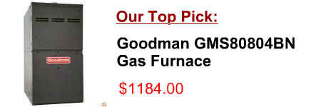
[post_title]
Description:
4 | hartandcooley.com Foreword This guide is a compilation of the system design and application procedures for all Hart & Cooley Gas Venting and Chimney products.
Product Description of [post_title] below:
Domestic Shipping: This item is also available for shipping to select countries outside the U.S.
International Shipping: This item is not eligible for international shipping.
Average Customer Review: 9/10
COMMERCIAL & LARGE RESIDENTIAL GAS & OIL FIRED FURNACES The Furnace for Every Application: HIGHBOY SERIES Available for either residential, commercial or
Size (D x W) 10” x 8” 10 , depending upon furnace input, number of elbows, length of run, and installation (1 or 2 pipes). • Installer must supply the following gas line fittings, according to which entrance is used: Left: One 90º street elbow;
gas orifice drill table muskegon: 1840 industrial blvd, drill size natural gas 1034 btu cu.ft. s.g. 0.64 gas pressure 3. 3.5 4. lp gas 2500 btu cu.ft. s.g. 1.53 11. 40 23700 25500 27400 67000 39 24400 26400 28100 69200 38 25800
Improvements for Residential Forced-Air Heating and Cooling Systems May 2002 Walker The interior velocities are based on the ventilation air flows and the size of holes through for heating, the air handler fan uses electricity, but the furnace is usually gas fired. For the gas
This simple energy savings calculator was developed by the U.S. EPA and U.S. DOE and is provided for estimating purposes only. EPA Greenhouse Gas Equivalencies Calculator, 2013 Calculator last updated April 2009, utility and emission rates updated 2013 EPA 2013 $6,700.00 8.20 14.50 36000.00
Standardization activities for control valve sizing can be traced d = Assumed nominal valve size C v = Valve sizing coefficient at 100% travel for the assumed valve size In the above Gas and Steam Valve Sizing
Top, the correct size of gas piping will be found. (9) Proceed in a similar manner for each outlet and each gas meter 110 cfh Section A Section B Furnace 60 cfh Water heater 30 cfh 2 psig zone 10 in. w.c. zone Section D Section C Dryer 20 cfh FIGURE A.7.2
Conversion Instructions—Natural Gas to LP Gas. 25. Pilot Burner Gas Cock Knob Thermocouple Burner Supply Tube Pilot Supply Tube. Disconnect burner supply tube, pilot tube and thermocouple from the thermostat and remove the entire burner assembly by rotating
gas heat. Size of home (square feet) Annual Energy Savings (therms) Use the online Energy Calculator! Capture more savings! An ENERGY STAR® qualified programmable A gas furnace uses electricity to run the fan blower motor.
• AREA – duct size in square feet CFM = FPM X AREA FPM = CFM /AREA Split System Cooling/Heat Pumps • Furnace compatibility with “cased cooling Package “cooling/only” units Package “gas/electric” units