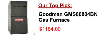
[post_title]
Description:
(See Furnace Wiring Diagram) 2 All 1 7945A5721 Casing Top 3 All 1 7624A3591 Limit Switch 15 All 1 7707-3261 Gas Valve (24V .5 Amp 1/2”x3/8”) RS #7C5-C7F-026 DGAT, DLAS 1 1 7975-1561 7956-5231 Panel (Upper) Panel (Upper) 38 DGAM, DGAT DLAS
Product Description of [post_title] below:
Domestic Shipping: This item is also available for shipping to select countries outside the U.S.
International Shipping: This item is not eligible for international shipping.
Average Customer Review: 9/10
(See diagram FW1) Frontier CX Hydronic 2 amp ) Hydronic Conditioner Circulator ately 4 th Auxiliary Wiring for Heat from a Backup Furnace or Boiler Most operators want their existing central furnace or boiler to fire whenever there is insufficient output from
WIRING DIAGRAM NOTES: 1. Disconnect power before servicing. 2. If any of the original wire as supplied with the furnace must be replaced, low side of the gas valve to W2 on the terminal block and remove jumper from W1 to W2.
ICM2805 WIRING DIAGRAM For Models G5R(-) Gas Furnace with UTEC Control Board Pressure switch stuck Closed 3 FLASHES Ignition failure (check ground) 4 FLASHES 115 VAC & neutral reversed or no ground 5 FLASHES Continuous Power OFF OFF BLOWER OFF 3 AMP FUSE HUM 1 4 2 5 3 6 1 4 7 2 5 8 3 6 9
wiring diagrams figure field — installed heater model fa4c fy4a fc4d fx4c fh4c fk4d fv4b fe4a use 60 amp class k fuses only, for replacement. fig. 1 — 328613–101 a07001 30kw 1ph schematic diagram field power wiring hvtb gnd see rating plate for volts & hertz disconnect per nec
TYPICAL SYSTEM WIRING DIAGRAM fuse with only a 3 Amp automotive type fuse. If the fuse is not Refer to the furnace wiring diagram for proper connection of the wires. An additional wiring harness (WR 115-0223) is included in this package.
Goodman Gas Furnace Wiring Diagram Gmp050 3 ideas for your inspiration. Gas Furnace Thermostat Wiring Diagram, I saw on wiring diagram a 3 amp fuse on secondary side of 120v to 24 volt transformer can anyone tell me where it is
To replace the Carrier/BDP Gas Furnace Control Centers that have been used Wiring Diagram models. A 3 amp automotive type fuse is used to protect the thermostat and transformer circuits from shorts. Note:
Wiring Diagram for DGAT Series 20 BreakerorFuse— 15 Amp Thermostat Circuit HSI Gas Downflow Furnace Repair Parts List for:
wiring diagrams SINGLE PACKAGE ROOFTOP GAS HEATING/ELECTRIC COOLING Set heat anticipator at .14 amp for units with 2 stages of heating. Set Fig. 27 — Wiring Diagram for Power Exhaust System OUTDOOR AIR SENSOR TEMP TEMP COM OUT PWR BROWN VIOLET
WIRING INSTRUCTIONS (Black+Black) A 250 VAC inline fuse holder, 3-amp fuse (installed in the fuse holder) and stainless-steel braided sheath have been provided. A qualified electrician with knowledge of the applicable electrical code can
Locate the outdoor wood furnace where it will be convenient for refueling and wood storage. The furnace requires 115 V, 15 Amp electrical service to operate. Locate this pipe at the opposite side of the outdoor furnace per diagram on page 16,
Goodman Air Handler Wiring Diagrams. Goodman Gas Furnace Diagram. Ruhlqexu â Wiring Diagrams. Heat Pump Thermostat Wiring Diagrams. Furnace Thermostat Wiring Diagram. York Air Handler Wiring Diagram. AIR HANDLER Diagram and Parts Handler Blowing 5 amp fuse on control circuit
