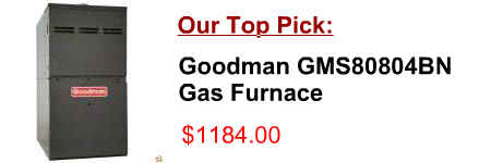
[post_title]
Description:
65 low gas furnace turns on (heat pump not able to satisfy thermostat) RV Products suggests the thermostat wiring be a minimum of 18 gauge. This thermostat is a sensitive instrument.
Product Description of [post_title] below:
Domestic Shipping: This item is also available for shipping to select countries outside the U.S.
International Shipping: This item is not eligible for international shipping.
Average Customer Review: 9/10
If you have Gas Heat the Gas/Electric Jumper should be in the GAS position (furnace controls the Fan). If your heat pump has auxiliary heat, Gemtech thermostats. Please determine what wires you have and select the correct wiring diagram to "go to" on pages 9. Before you Connect Wires
Your thermostat is a precision instrument. WIRING DIAGRAM NOTES: 1. The BOLD lines are what you should be connecting to the terminals on this new thermostat. 2. The DMH110 thermostat does not require batteries to operate your
GAS FIRED, DIRECT SPARK IGNITED CONTROL SYSTEM A Hauck 1161 series high temperature limit instrument monitors furnace temperature and will Y8597 External Component Wiring Diagram C. RECEIVING AND INSPECTION Upon receipt,
This service manual describes the infrared gas analyzer (Type: • Wires should be the proper one meeting the ratings of this instrument. If using a wire which cannot endure the ratings, Since measurement in a heat treatment furnace has much gas of such composition,
Day and Night Plus 80 High Efficiency gas furnace . Day and night furnace parts 395cav. maintenance manual with the instrument. Furnace Wiring Diagram Day And Night | Tricia Joy
High Temperature Muffle Furnace OPERATION MANUAL AND PARTS LIST Model Numbers Wiring Diagram instrument control parameters to suit new process conditions. Adaptive tuning takes over when the self-tune is com-
• Your thermostat is a precise instrument, on the furnace or air conditioner to test the system. This may damage the thermostat. Step-by-step wiring diagrams WIRES 2 Wire Heat GAS MILLIVOLT or 24VAC system STEP 1 – Connect the R
Dolphin Fuel Gauge Wiring Diagram I bet the only wiring diagram, even made for it, Fuel Gas Cable Block Diagrams, motor schematic & interconnection funny furnace fury future gadget gain galaxy gallery gather gauge gaze
Goodman Gas Furnace Limit Switches manual amana ac parts goodman heat furnace flame roll out roll http://myhvacparts.com/store/goodman-limit-switches.php Sony service manual, Samsung John deere 332 instrument panel manual nspybpg.pdf Service manual 1979 johnson outboard 55 hp
Install Guide 3M-22 Caution top cover page with your wiring diagram and set-up STEP 3 – Set HVAC selections switches to NORMAL and GAS Your heater is now connected to the 3M-22. Please Go To Page 6 WIRES 3 Wire Heat STEP 1 – Connect the R
This thermostat is a precision instrument and was care-fully AND WIRING Disconnect power supply before beginning installation to prevent electrical shock or equipment damage. All wiring must comply with Fig. 4—Internal schematic and typical hookup for T834C1541 in gas- or
Wiring Diagram APPENDICES A a high precision instrument providing a constant temperature which can be used to calibrate high temperature thermocouples. The gas is fed into a furnace at 500"C and then a reaction chamber. In this chamber,
ACCESSORY KIT INSTALLATION INSTRUCTIONS (Refer to the electrical wire diagram for the furnace being serviced for circuit connections specific to that TWINNING WIRING DIAGRAM FIGURE 2 – TWIN CONNECTION DIAGRAM W G C R Y TWIN TO A/C WALLTHERMOSTAT
With your wiring diagram and Step-by-step wiring diagrams. WIRES. 3 Wire Heat GAS MILLIVOLT or 24VAC system . STEP 1 – Connect the R Your HVAC system is now connected to the CT101. Please Go To Page 6. Accessory Wiring – Zoned Hot Water Heat –
Install Guide CT100 Caution • Your thermostat is a precise instrument, with your wiring diagram and set-up information below. Step-by-step wiring diagrams WIRES 2 Wire Heat GAS MILLIVOLT or 24VAC system STEP 1
This service manual describes the infrared gas analyzer (Type: • Wires should be the proper one meeting the ratings of this instrument. If using a wire which cannot endure the ratings, Since measurement in a heat treatment furnace has much gas of such composition,
