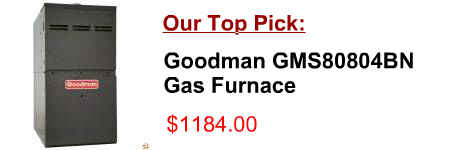
[post_title]
Description:
Plan furnace gas supply piping so it will not interfere with Wire fu rnace according to the Field Wiring Diagram shown in Figure 25, local codes, 4. If Horizontal, is furnace level or tilted toward burner up to 1/4”. 5.
Product Description of [post_title] below:
Domestic Shipping: This item is also available for shipping to select countries outside the U.S.
International Shipping: This item is not eligible for international shipping.
Average Customer Review: 9/10
RESIDENTIAL GAS FURNACE MODELS: TG9S*MP, GG9S*MP WIRING DIAGRAM . . . . . . . . . . . . . . . . . . . . . . . . . . . . . . . . . . 39 A gas-fired furnace for installation in a residential garage must be installed so the burner(s)
The following charts depict the thermostat control wiring, ceiling assembly wiring destinations, and relay functions for air conditioners with control boxes containing individual relays. Strip if the thermostat is operating a gas fired furnace.
Roof top air conditioner and any furnace with a 12 VDC control circuit. The following charts depict the thermostat control wiring, ceiling assembly wiring destinations, and Voltage Terminal Strip if the thermostat is operating a gas fired furnace.
Sizing Guide For Beacon/Morris Gas Unit Heaters 1.Choose your Application & Temp † Garage † Post Frame † Warehouse † Greenhouse † Garage † Post Frame
# 45466K003 Page 1 INSTALLATION INSTRUCTIONS G1D91BU, G1D93BC, G1D93BU, CG90CB, & CG90UB High Efficiency 90+ Condensing Gas Furnace Manufactured By
Wiring.Diagram.. 30 Accessories Ceiling fans can create drafts that alter burner flame patterns. Altered burner Gas.furnace. . _____ Btu/Hr. Vented.gas.heater. . _____ Btu/Hr
Wiring Diagram (Electric or Gas Heat) HH or Purple (7000 Series Furnace Blower High HL or Brown (7000 Series Thermostat Only) Brown Wire for Gas Furnace Motor Low Speed if So Equipped Furnace Blower
Goodman Gas Furnace Wiring Diagram. Furnace Wiring Diagram. Whirlpool Refrigerator Wiring Diagram. Electric Water Heater Wiring Code >>>CLICK HERE<<< Use only 10gauge wire and 30 amp circuit breaker with Energy Smart 119 gallon capacity. and sauna wiring, Ceiling fans, Water heater
80% GAS FURNACE INSTALLATION INSTRUCTIONS GAS FURNACE SAFETY Table of Contents The installation of the furnace, wiring, warm air ducts, venting, See the Wiring Connection Diagram in
Coleman Evcon Electric Furnace Wiring Diagram. FUNCTIONAL (air distribution box / ceiling assembly). adds 5,600 btu heating output to your air conditioner. Evcon Furnace Parts Diagram · Coleman Evcon Gas Furnace Air Conditioner System. Coleman EB20D
ELECTRIC FURNACE MODELS: EB INSTALLATION MANUAL ISO 9001 Certified Quality EB10* Wiring Diagram . . . . . . . . . . . . . . . . . . . . . . . . . . . . . . . . . . . .10 the floor or the ceiling must be sealed to prevent air
Gas Furnace Electric Furnace Mounting Holes directly to the front of the Electric Furnace. AIR INLET ATTIC CEILING DUCT SYSTEM FLOOR REGISTER ROOF BLOWER FURNACE ROOF JACK ROOF SEALANT FRESH AIR BACK OF FURNACE VentilAire IV Wiring Diagram. 6 CAUTION:
Trane Air Conditioning and Gas Furnace, Trane Weathertron. york Or cooling requirements furnace wiring diagram cleaning furnace. Trane TRANE THERMOSTAT XL900 DIGITAL THERMOSTAT MANUAL. Format : PDF HUNTER CEILING FAN 3 SPEED SWITCH WIRING DIAGRAM. Format : PDF Auto Temp Heat Pump
COLLECTION GAS FURNACE UPFLOW / HORIZONTAL AIR DISCHARGE 506610−01 05/2011 multiple furnace installation may use a group of up to Use the provided unit wiring diagram and the field wir-
In order to prevent water damage to the finished ceiling below. HORIZONTAL APPLICATIONS Upflow and Downflow furnaces GAS PIPING The upflow/ horizontal furnace is shipped standard for notes on the furnace wiring diagram (found in the SER-
Sizing Guide For Beacon/Morris Gas Unit Heaters 1.Choose your Application & Temp † Garage † Post Frame † Warehouse † Greenhouse † Garage † Post Frame
wiring diagrams figure field — installed heater model fa4c fy4a fc4d fx4c fh4c fk4d fv4b fe4a fe5a 1 kfceh0401n03 018—024 018—024 018—024 018—024 001 1 kfceh0501n05 018—060 018—060 018—060 018—060 001 30kw 1ph schematic diagram field power wiring hvtb gnd see rating plate
CG80UB, CG80RB, & CG80TB 80% Gas-Fired Furnace. Page 2 of 20 Issue 0937 506183-01 One opening shall be located within 12" of the ceiling and the other within 12" of the floor, Refer to the furnace wiring diagram for specific connection information.
