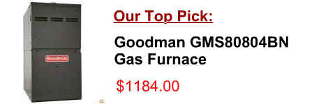
[post_title]
Description:
RESIDENTIAL GAS FURNACE MODELS: TG9S*MP, GG9S*MP (95.5% AFUE Single Stage Multi-position) Wiring Diagram . . . . . . . . . . . . . . . . . . . . . . . . . . . . . . . . . . . . . 39 by the side wall horizontal vented gas fueled equipment.
Product Description of [post_title] below:
Domestic Shipping: This item is also available for shipping to select countries outside the U.S.
International Shipping: This item is not eligible for international shipping.
Average Customer Review: 9/10
90 HORIZONTAL GAS FURNACE INSTALLATION INSTRUCTIONS GAS FURNACE SAFETY When installing a WEC coil in a horizontal position with a horizontal gas furnace, See Wiring Connection Diagram. Gas Control Valve
Upflow/ Horizontal Downflow/Horizontal Condensing, Direct Vent Gas-Fired Furnace PUB. NO. 22-1836-08 XR 95 TUH1B040A9241A, TUH1B060A9361A,
Horizontal Right or Left Gas-Fired Furnace XT 80 TUD1A040A9H21B, TUD1B060A9H31B TUD1B080A9H31B, TUD1C080A9H41B TUD1-H Wiring Diagram For Gas Furnaces From Dwg. D342489 Rev. 6. 22-1779-08 13 Electrical Data TUD1-H Schematic Diagram For Gas Furnaces
Upflow/ Horizontal Downflow/Horizontal Condensing, Direct Vent Gas-Fired Furnace PUB. NO. 12-1329-03 AUH2B060A936VA, AUH2B080A942VA,
diagram attached to furnace diagram attached to fur-nace. Primary drain vent stack GAS PIPING The upflow/ horizontal furnace is shipped standard for Upflow/Horizontal and Downflow/Horizontal Gas-Fired Condensing Furnaces Models TUC1, AUC1, TDC1, ADC1
80% SINGLE STAGE GAS FURNACES Part Number minal within a horizontal distance of 2′ (61cm) from the cent-erline of the terminal * E Clearance to an unventilated soffit * Refer to Furnace Wiring Diagram for location of the heating
Single Stage High Efficiency Gas Furnaces INSTALLATION INSTRUCTIONS GUH80A UpFLOw / HORIzONTAL FURNACE GDD80A DOwNFLOw FURNACE 80+ AFUE DO NOT DESTROY THIS MANUAL.
Downflow/Horizontal Condensing, Gas-Fired Furnace XB 90 TDC1B040A9241A, TDC1B060A9361A TDC1B080A9421A, TDC1C100A9481A TDC1D120A9601A Single-Stage Fan Assisted
RESIDENTIAL GAS FURNACE WITH ECM MOTOR MODELS: TP9C*C, YP9C*C, CP9C*C, LP9C*C served by the side wall horizontal vented gas fueled equipment. Use the wiring diagram below to c onnect the furnace control, Communi-
Page 6 Installer’s Information Manual ATTIC INSTALLATION Line contact is permissible for furnaces installed in horizontal positions. The intersection of furnace top and
A gas-fired furnace installed in a residential garage must be installed so the burner(s) and the ignition source are Refer to the wiring diagram supplied with your vertical furnace unit for all electrical connections. Figure 19. 22 IV. OPERATION
Hydro flameTM 8500-IV Series Furnace MODELS 8516, 8520, 8525, 8531, 8535 Technical Installation Manual 9 Horizontal and Vertical Door Option for gas supply connection to furnace. The gas supply line of the fur-
FURNACE SURFACE VERTICAL CLOSET HORIZONTAL CLOSET HORIZONTAL ALCOVE / ATTIC SIDES 0" 1" 0" diagram attached to furnace diagram attached to fur-nace. Primary drain vent stack HORIZONTAL FURNACE GAS PIPING MAY BE FROM EITHER SIDE (UPFLOW SHOWN)
33-3/8" 80% Gas Furnace Units • Refer to Service Manual RS6610004 for installation, The vertical height of the Category I venting system always refer to the wiring diagram on the unit for the most up-to-date wiring.
